1 Product Introduction
This system comprehensively monitors the status parameters of distribution network switchgear and ring main units.
1) Monitors partial discharge,
2) Monitors temperature, and
3) Monitors leakage current of shielded wires.
This system uses ultrasonic and transient ground wave partial discharge detection technology, and is suitable for real-time monitoring and alarm of partial discharge signals in ring main units and outdoor switch boxes. It features high sensitivity, strong anti-interference performance, and multiple communication methods.
This system deploys intelligent dual-function wireless partial discharge sensors (AE, TEV) in conjunction with data acquisition devices to monitor partial discharge signals in the cabinet during operation in real time. By setting test thresholds, performing spectrum analysis, and displaying graphs, users can easily determine whether the equipment has partial discharge. Based on its long-term trends, it can detect potential faults earlier, transforming the previous passive detection method into proactive “defensive ” monitoring. This makes the switchgear products safer and more reliable, and also adds new technological highlights to the products.
The partial discharge online monitoring device mainly consists of a front-end ultrasonic (AE) and transient ground wave (TEV) dual-wireless sensor, a partial discharge acquisition device, a wireless intelligent gateway, and online partial discharge analysis system software. The front-end wireless partial discharge signal acquisition sensor is installed inside the cabinet by magnetic attraction. The wireless intelligent sensor itself has signal filtering, amplification, and analog-to-digital conversion functions, which can filter, reduce noise, and amplify the sensor-coupled signal, acquire the transient ground wave discharge signal and ultrasonic discharge signal coupled by the sensor, acquire the partial discharge signal through the wireless receiving device, and send it to the server for processing.
The power distribution partial discharge acquisition device (main unit) uses LORA to… The system communicates with partial discharge (PD) sensors via various communication methods. The collected data is aggregated through edge computing and then transmitted to the power distribution smart gateway. It possesses PD edge computing and data storage capabilities. PD data processing is moved to the edge, reducing the transmission and processing load on the server, enabling local real-time processing and improving on-site response time. Even after a network outage, it can continue normal operation, monitoring, storing, and computing PD data on-site. Once the network is restored, the cached data can be synchronized to the cloud server, ensuring information integrity.
In addition to partial discharge monitoring, this system can also monitor the temperature of the plugs in ring main units and the T-type connectors in switchgear.
For monitoring the temperature of the ring main unit’s plug, this system uses a passive wireless temperature sensor powered by a high-voltage electric field. This sensor requires no built-in battery, no external power supply, and no conductor current. It powers the chip using an electric field at 10kV, and the monitored temperature data is transmitted wirelessly.
T-type connector in the switchgear, this system uses a passive wireless temperature sensor powered by current sensing. This sensor does not require a built-in battery or an external power supply. When the conductor current is above 3A, it powers the chip by sensing the current (conductor current ≥ 3A), and the monitored temperature data is transmitted wirelessly.
In addition to partial discharge monitoring and temperature monitoring, this system can also monitor the leakage current of the cable shielding grounding wires of ring main units, switch cabinets, and transformer substations.
Because the shielding current is too small, monitoring it is difficult, so open-type current transformers cannot be used; only closed-type current transformers can be used. Furthermore, a local digitization method must be adopted, adding a data acquisition circuit composed of a microcontroller, AD converter, and other electronic circuits to the current transformer to acquire the weak current signal, process it using an FFT algorithm, and then transmit it via a data bus.
1.1 Scope of application
This system is applicable to partial discharge monitoring, temperature monitoring, and leakage current monitoring of ring main units, switchgear, wind farm transformer substations, photovoltaic transformer substations, and their internal high-voltage equipment at voltage levels of 10KV and above.
1.2 Usage Environment
1) Altitude: Below 4500M.
2) Ambient temperature: -40℃~+80℃.
1.3 Product Features
- Distributed layout, highly scalable
The system monitors the networked layout of terminals. When adding or removing terminals on the existing layout, the system automatically identifies and configures them without any additional settings.
- Real-time monitoring
The system records real-time data from each monitoring node, and the monitoring cycle can be flexibly set.
- Timely warning
When a node detects an abnormal local volume, it will quickly report it to the monitoring server. The server software will record the necessary information and issue an alarm.
- Impact resistance
It can withstand a 600KV flashover impact without damaging terminal equipment or losing data.
- Anti-interference
It possesses time-domain and frequency-domain signal analysis technology, which can effectively separate interference signals and partial discharge signals, and effectively avoid interference at the instrument’s power supply end.
- Stable transmission
With the help of a powerful mobile network, data can be directly transmitted to the server, with reliable transmission performance and low network latency.
- Good access security
The system connection does not affect the sealing and insulation performance of the switchgear, nor does it affect the safe operation of the equipment.
9) EMC rating
Electrostatic discharge immunity: Level 4
Electrical Fast Transient/Bulk Immunity: Level 4; Surge (Impulse) Immunity: Level 4
Power frequency magnetic field immunity: Level 5
2 Measurement principle and hardware composition
2.1 Partial discharge measurement principle
When high-voltage switchgear and its internal high-voltage equipment (such as PT, CT, busbars, cable joints, etc.) experience partial discharge due to insulation faults, the partial discharge process is often accompanied by physical or chemical phenomena and corresponding processes such as pulse current, electromagnetic waves, ultrasound, light, ozone, and heat. When we test, ultrasound and TEV are the main detection indicators.
Partial discharge monitoring techniques include ultrasonic methods and TEV methods.
- The ultrasonic method uses an ultrasonic sensor to receive the ultrasonic signal emitted by partial discharge (PD) as the basis for PD detection. The detection frequency band is typically 20kHz to 100kHz. The biggest advantage of the ultrasonic method is that it uses ultrasound as the monitoring signal, avoiding various electromagnetic interferences at the PD monitoring site, thus gaining widespread application. Ultrasonic detection originated in the 1940s, but it was not widely adopted due to low sensor sensitivity. With advancements in acoustic emission technology, the sensitivity of ultrasonic transducers has been significantly improved, and thanks to the rapid development of integrated circuits and signal processing technology, the ultrasonic method has regained popularity. Now, the ultrasonic method has become an important method for PD detection.
- The TEV method is a novel partial discharge detection method, increasingly used in high-voltage switchgear. When partial discharge occurs in a switchgear cabinet, the generated electromagnetic waves propagate outwards from the discharge point. Because the switchgear cabinet’s metal structure is not continuous, it cannot completely shield the electromagnetic waves. These waves propagate through gaps in the switchgear cabinet, cable insulation terminations, and other discontinuous metal parts to the outside of the switchgear’s metal shielding shell. When the electromagnetic waves reach the outer surface of the metal shell, a brief voltage to ground is generated, called the transient ground voltage. The rise time of the transient ground voltage is only a few nanoseconds and disappears quickly. In practical applications, the TEV sensor is placed on the inner wall of the switchgear cabinet, with a detection frequency range of 3MHz to 100MHz. The TEV method has high sensitivity to internal discharges.
The system adopts a modular design approach, using ground wave sensors and ultrasonic sensors to detect faults within the switchgear body.
The system detects transient ground wave signals and ultrasonic signals. The analog signals of the transient ground wave signals and ultrasonic signals are filtered, amplified, and converted from analog to digital by the detection circuit. After high-order digital filtering, the signals are transmitted by the processor to the wireless data relay unit via wireless signal, and then transmitted to the backend through various communication interfaces.
Each set of partial discharge data collected by the unit is labeled with corresponding time parameters based on whether a time stamp signal or phase signal is input. After processing by the algorithm, the data is first stored locally, and then sent to the server according to the server-side software instructions. This ensures the systematic nature of the data, does not miss characteristic signals such as partial discharge signals, and does not cause communication congestion.
The unit calculates the peak and effective values of the partial discharge signal for each measurement cycle set by the system, adds a timestamp, and transmits it to the server software.
I. Ultrasonic Testing
Based on the principle of acoustic emission (AE), ultrasonic sensors are used to collect ultrasonic signals emitted during partial discharge of electrical equipment. The sound waves generated by electrical equipment during discharge have a wide frequency spectrum, ranging from tens of Hz. Signals with frequencies up to a few MHz and below 20 kHz can be heard by the human ear, while ultrasonic signals with frequencies higher than this can only be received by ultrasonic sensors. By detecting the amplitude, phase, frequency, noise, etc. of the sound signal, as well as its relationship with the operating (applied) voltage, based on the relationship between the energy released by the discharge and the sound energy, the degree and location of insulation defects in electrical equipment such as switchgear can be effectively reflected.
The principle of ultrasonic testing is shown in Figure 2.1.
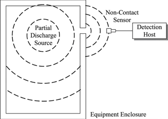
Picture 2.1 Ultrasonic (AE) Detection Principle
II. Transient ground wave detection
Transient ground wave partial discharge monitoring is based on the 3-100MHz frequency range, which is rarely emitted by normal power equipment. The basic facts of transient electromagnetic signals. When partial discharge occurs inside switching equipment, electromagnetic waves are generated. These electromagnetic waves can only propagate out through the channels between the metal casings of the switch cabinet. These channels may be gaps, gaskets, or other insulating components between the metal casings. When electromagnetic waves. (TEV) is simultaneously generated on the metal enclosure of the switch cabinet, which can be measured by a sensor placed on the metal enclosure.
The principle of transient ground wave detection is shown in Figure 2.2.
Picture 2.2 Transient Ground Wave (TEV) Detection Principal Diagram
2.2 Temperature measurement principle
I. High-voltage electric field induction power extraction principle
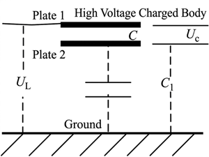
Figure 2.3 Schematic diagram of electric field space power extraction principle
This sensor is powered by high-voltage electric field induction. This power extraction method differs from the current-sensing CT power extraction method. Current- sensing CTs require current in the power extraction line; if there is no current or the current is too low, power cannot be extracted, and the equipment cannot operate. High-voltage electric field induction power extraction does not require current; only a high voltage is needed. Its working principle is shown in Figure 2.3.
II. Current Induction Power Extraction Principle
The current-induction power harvesting device consists of two parts: an energy harvesting transformer and an energy harvesting power module. Its working principle is shown in Figure 2.4.
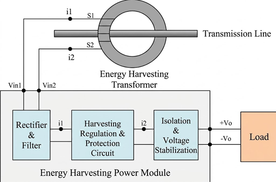
Figure 2.4 Schematic diagram of current induction power extraction principle
This device obtains electrical energy from the transmission line through an energy harvesting transformer, and then inputs it into the energy harvesting power module. The energy harvesting power module rectifies and filters the energy and achieves isolated and regulated output. The energy harvesting power module contains a power extraction regulation and protection circuit, which can adjust and limit the electrical energy input to the module in real time, absorb instantaneous large currents, and ensure that the module can still output a stable voltage when the current in the transmission line is unstable.
2.3 Leakage current measurement principle
Because the shielding current is too small, monitoring it is difficult, so open-type current transformers cannot be used; only closed-type current transformers can be used. Furthermore, a local digitization method must be adopted, adding a data acquisition circuit composed of a microcontroller, AD converter, and other electronic circuits to the current transformer to acquire the weak current signal, process it using an FFT algorithm, and then transmit it via a data bus.
3 Hardware Components
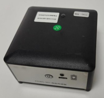
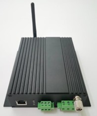
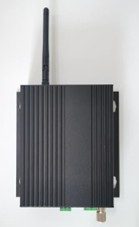
3.1 Partial discharge acquisition device
I. Basic Functions of Partial Discharge Acquisition Device
- It has the function of saving and exporting detection data.
- It has a self-test function and the ability to upload the self-test signal to the monitoring terminal unit.
- Upload interface with the smart gateway supports wireless or RS485. Interface, supports Modbus. The communication protocol can upload alarm signals such as monitoring data, partial discharge anomalies, and spectrum diagrams to the monitoring terminal unit in accordance with standard protocols.
- The all-aluminum body design effectively improves heat dissipation performance.
- The optional DC power supply terminal block can be connected to 1mm² multi-strand flexible wire.
- The product operates stably and has a service life of no less than 10 years under normal conditions.
- rail mounting and wall mounting, to suit different application environments.
II. Technical Parameters of Partial Discharge Acquisition Device
1) Power supply voltage: AC/DC 85-265V, 50Hz/60Hz, or DC 24 ~ 48V ± 20%, power < 9W.
2) Working environment: Temperature: -40 ℃ ~85 ℃; Humidity: ≤99%.
- Protection rating: IP65.
- Sensor communication method: wireless LoRa Acquire transient ground radio / ultrasonic information;
- Communication interfaces: Includes RS485, Ethernet, and USB. Communication interfaces, etc.
- External dimensions: 153mm × 147mm × 42mm
Smart 2-in-1 Sensor
I. Overview
Partial discharge sensors are classified into ultrasonic sensors, transient ground voltage sensors, and ultrasonic / transient ground voltage combined sensors, configured according to actual engineering needs.
- Using TEV and AE The detection principle involves real-time acquisition and processing of transient ground wave partial discharge signals and ultrasonic signals.
- Communication method: Wireless LoRa.
- The protection level reaches IP65.
- The sensor uses a magnetic attachment, allowing it to be mounted and fixed to various cabinets. The sensor surface fully adheres to the surface of the cabinet being measured. The sensor has anti-slip teeth to prevent shifting after installation. The sensor should be small in size to minimize space occupied within the cabinet after installation.
- The product operates stably and has a service life of no less than 10 years under normal conditions.
Wireless ultrasonic / transient ground voltage dual-mode sensor
II. Technical Parameters of Ground Electric Wave / Ultrasonic Electromagnetic Sensor
- Temperature and humidity resistance: 40 ℃± 2 ℃ and 90%RH ± 3%RH, 24h; Operating ambient temperature: -40 ℃ ~85 ℃; Humidity: ≤99%.
- Frequency bandwidth: ground wave 3MHz-100MHz; ultrasound 20kHz-500kHz.
- Power supply: 3.7V, built-in battery;
- Sensitivity: ≥ 40dB.
- Linearity error: ≤ 20%.
- Measurement range: 0 ~ 60dB.
- Resolution: 0.1dB.
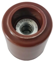
3.2 Wireless passive temperature sensor
I. Temperature sensor powered by voltage sensing
This temperature sensor uses the principle of voltage induction to obtain power. It is built into the insulating plug of the ring main unit accessory and is in direct and close contact with the heating point, so it can accurately reflect the temperature of the heating point.
| Temperature Sensor Parameters | |
| Temperature Measurement Range | -30℃~135℃ |
| Temperature Measurement Accuracy | ± (Standard Reading×1% + 1℃) |
| Resolution | 0.1℃ |
| Sensor Size | Built into an insulating plug |
| Power Supply | Inductive power, no battery required, CT |
| Measurement Cycle | Initial power-on time less than 20 minutes, measurement cycle less than 3 minutes |
| RF Standard | 2.4GHz |
| Transmission Distance: | 100M(open environment) |
| High Voltage Impulse | 15kV ± 10 times |
| Withstand Voltage | 15kV/3min,normal |
| Partial Discharge | 15kV, less than 10pc |


II. Temperature sensor for power generation in soft CT scan
| Parameters of the power-feeding temperature sensor for soft CT | |
| Temperature measurement range | -20℃~125℃ |
| Temperature measurement accuracy | ± (standard reading × 1% + 1℃) |
| Resolution | 0.1℃ |
| Power supply method | Power is drawn from current sensing, eliminating the need for batteries. |
| Minimum operating current | 3A |
| Radio frequency standards | 2.4GHz |

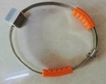

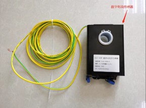
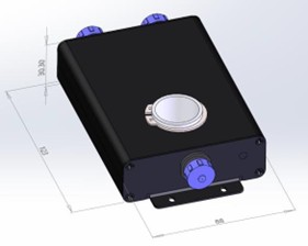
3.3 Digital current sensor
- DCT-100 Digital Current Sensor Measurement Range: 1mA~2000mA
- Accuracy: ± (1% standard value + 0.1mA)
4 Equipment photos
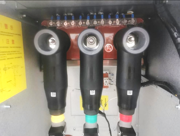
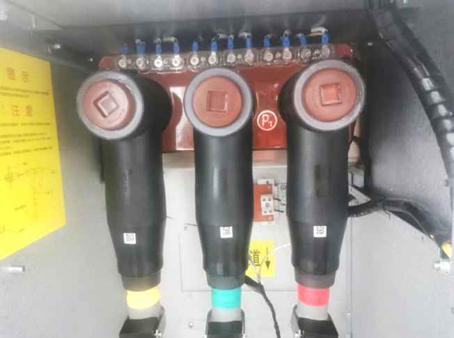
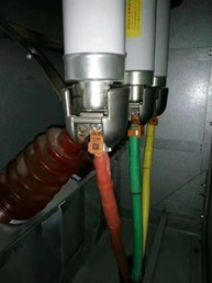
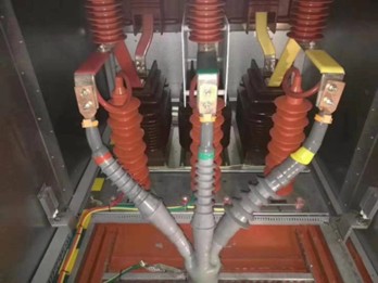
4.1 Wind power transformer
T shape connector, grounding wire, current sensor digital current sensor
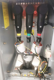
Internal equipment of wind power transformer
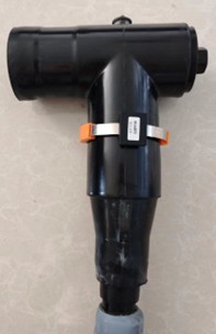
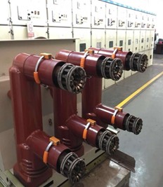
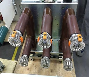
4.2 Ring main unit
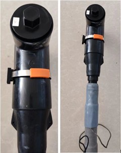
Ring main unit – before and after installing temperature-sensing insulating plugs
Ring main unit – after installing the temperature-sensing insulating plug and back cover
4.3 switch cabinet
- For more information about this product, please download the brochure from here, or contact Britop directly.
- Contact information:
- (For China market):
Sichuan Yachen Electric Co., Ltd.
Homepage: http://www.ycdqkj.com.cn
Contact: Mr. Xu
Tel (Wechat): +86 13088269292
Technical: +86 816 6394499
Commercial: +86 816 2311298
For international sale, please contact:
Qingdao Britop International Trading Co.,Ltd.
Website: https://qdbritop.com
Contact: Bright Meng
Email: britop@qdbritop.com - Tel (Wechat): +8613811458455